Programming of the Tiny85 can be done using an arduino or even a breadboarded ATMEGA328P. So I've done this using the onboard USB port on an arduino or a knock-off, and also using the FTDI chip.
The following should be carried out in this order:
The above steps are shown in this YT video: https://www.youtube.com/watch?v=VlUq2COFjj4&t=56s
To get the OLED running: https://github.com/datacute/Tiny4kOLED
Most times when using an LED either in a circuit or on it's own a resistor is required to limit the amount of current being delivered to the LED. We must know a few things going into this and then we can figure out what value resistor will be required. We need to know the Forward Voltage and the Foward Current of the LED and we need to know the supply voltage.

In the above schematic the LED specs are FV: 3V and FC: 20mA. Asuming the power source is 5V there is 2V left over. This is divided by the LED FC. So, to find R do the following:
R = V / I ~ 2V / .02A = 100Ω
V = I x R
I = V / R
When using ohm's law to find R, V or I make sure to use absolute values. 1.2k is 1200, 30mA is 0.03A, 800mV is 0.8V.
Other examples might use a 4.2V battery, a 9V battery or a 12V battery...
Let's say we have an LED which has these specs FV = 3.2V and FC = 30mA
|
Source (4.2V) - 3.2V = 1V R = V / I ~ 1V / .03A = 33Ω R = 33Ω |
Source (9V) - 3.2V = 5.8V R = V / I ~ 5.8V / .03A = 193Ω R = 193Ω |
Source (12V) - 3.2V = 8.8V R = V / I ~ 8.8V / .03A = 293Ω R = 293Ω |
I've long believed that the resistor must found for the total supply voltage. In reality the resistor must be found only for the voltage not consumed by the LED using the forward current of the LED. Wow. My LED's are so much brighter now. LOL 
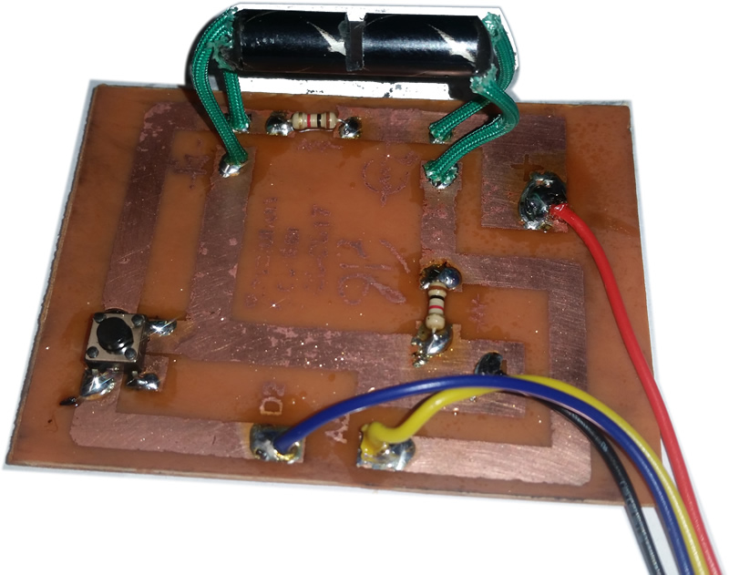 This revolution counter is actually just part of the equation. This board delivers power to a standard 3mm LED. It also supplies a small current to a photo-sensitive resistor. The LED and Photo-Resistor are mounted inside of the tube facing each other each are at their respective ends of the tube facing inward. When powered up the photo resistor will return to the micro-controller a value like 300. When the light stream from the LED is interrupted the signal goes from 300 down to about 0. When this happens we tell the micro-controller to add that to the tally as a single revolution and make the changes on the small OLED screen.
The wikepedia link here is obviously SMT info - https://en.wikipedia.org/wiki/Surface-mount_technology
